4K Cryostat
Project Overview
The goal of this project was to assemble a cryostat that would reach sub-4 kelvin temperatures so it could be used to test superconducting materials for quantum sensors, and to design housings for the chips mounted inside it. In this project I analyzed SolidWorks models, sent custom machining instructions, and learned about sealing vacuum systems and thermalizing cryogenic systems. I also further honed my SolidWorks modeling skills with the PCB housing design.
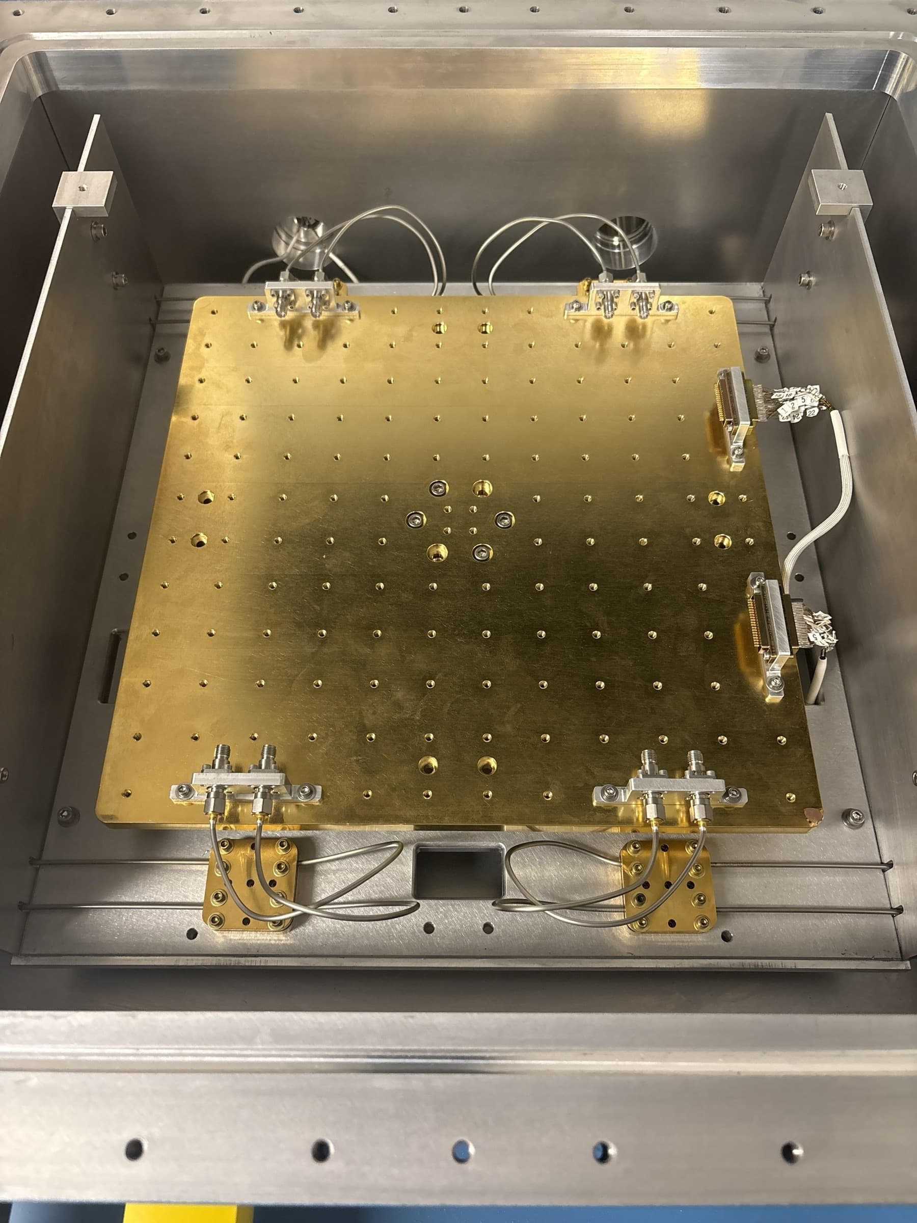
Although this project was mostly assembly, aside from designing the legs of the coldhead and the PCB housing, I learned a lot about cryogenic systems and still had to make thoughtful assembly decisions. The most important factor when thermalizing a system during assembly is maximizing surface contact between parts. Inside the vacuum, there's no air to carry heat between parts. Heat can only move where solid metal touches solid metal. Therefore, if two parts are bolted together but only touch at a few points, heat gets stuck, and the part never gets as cold as it's supposed to.
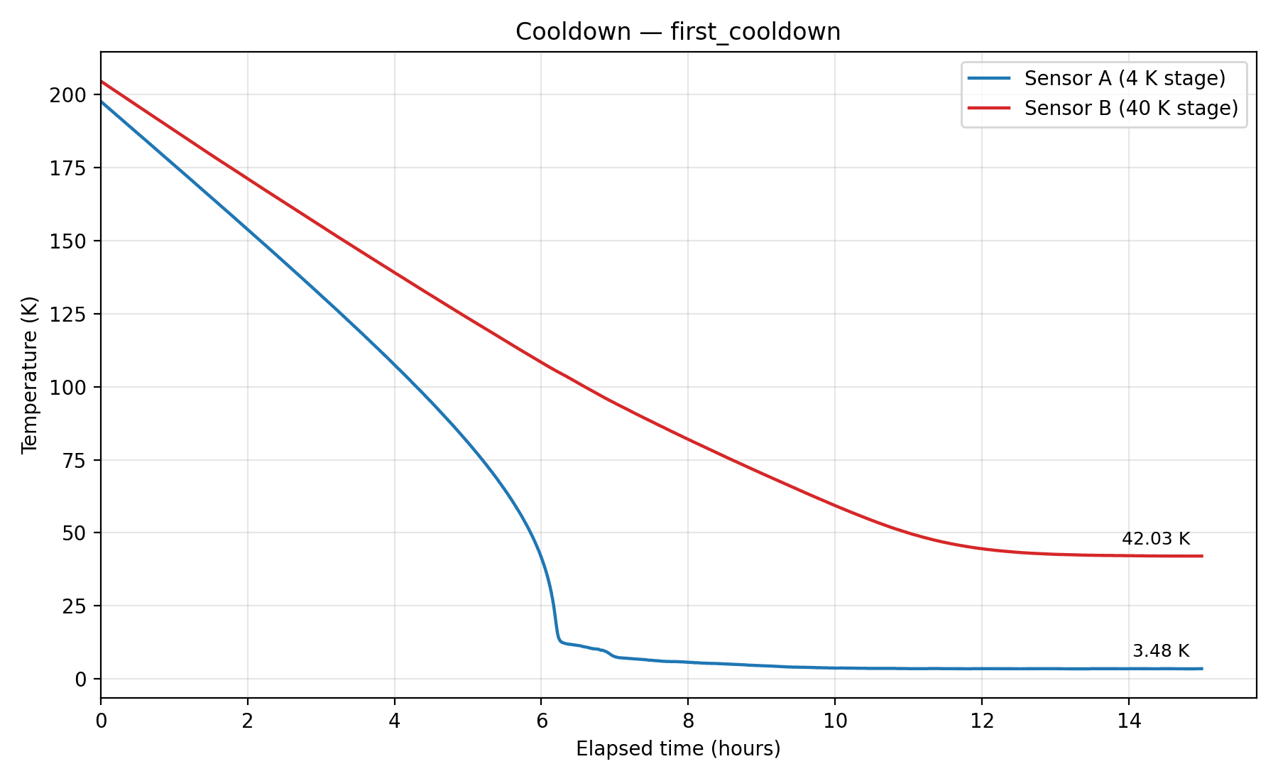
During assembly, component orientation, bolt tightness, and use of aluminum tape to block off potential openings were vital in ensuring the system stayed cold. These efforts paid off, as the system reached a final temperature of 3.48K (0.52K below the goal).
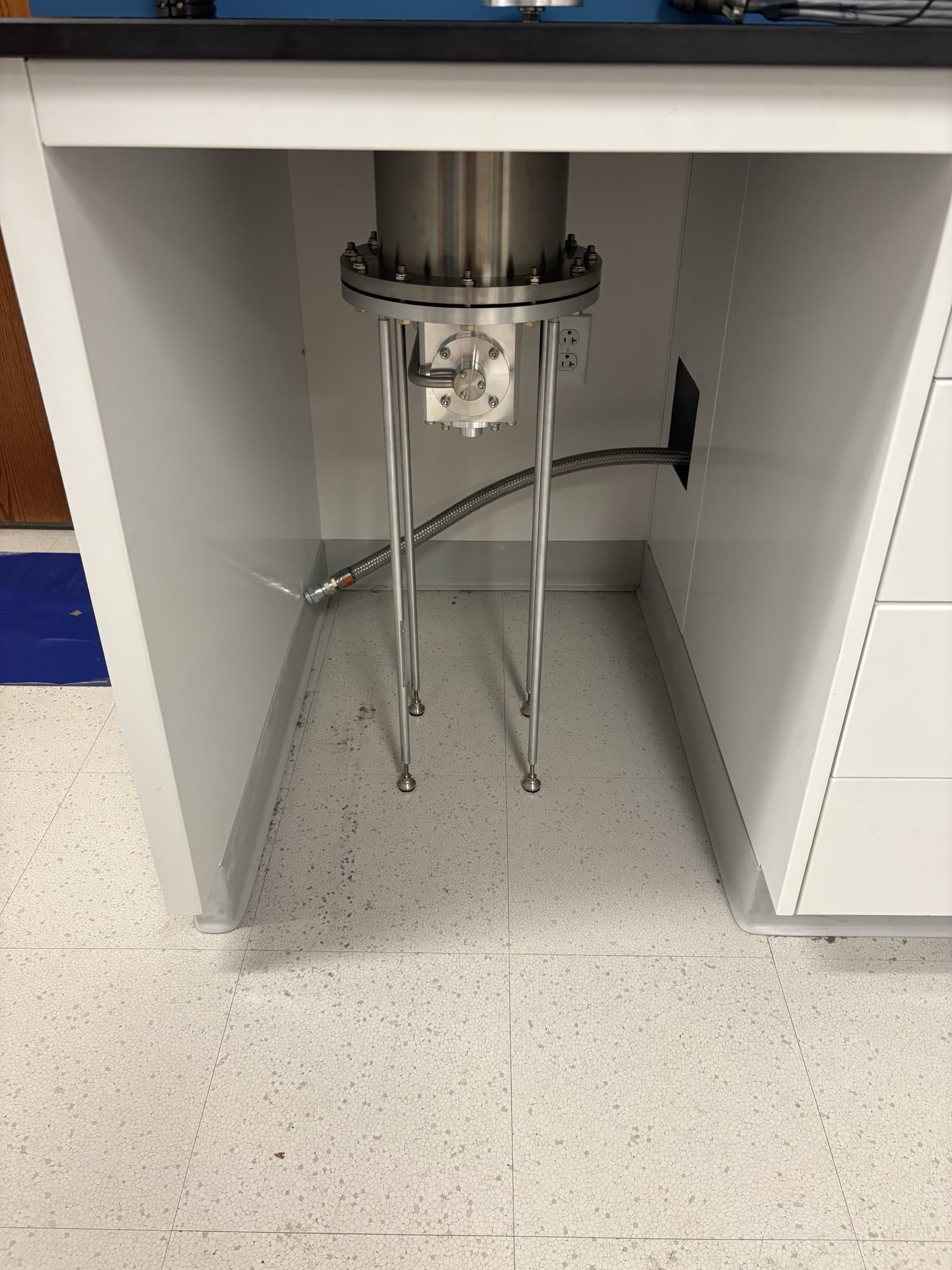
For the leg design, I had to measure out the height from the bottom of the coldhead mounting flange to the floor, determine the right material for the legs, source adjustable-height feet, and develop a mounting plan. For the leg material, I determined that aluminum would be best because the machine kept it in bulk and because it was more than strong enough to support the coldhead: the coldhead is 60 lbs, which divided among four legs, is 15 lbs per leg.
To mount the coldhead and install the legs, I used a lab jack and wooden blocks so that the flat part of the coldhead flange could stably sit on the jack. Once the coldhead was secured to the underside of the vacuum jacket, I was able to remove the jack and mount the legs.
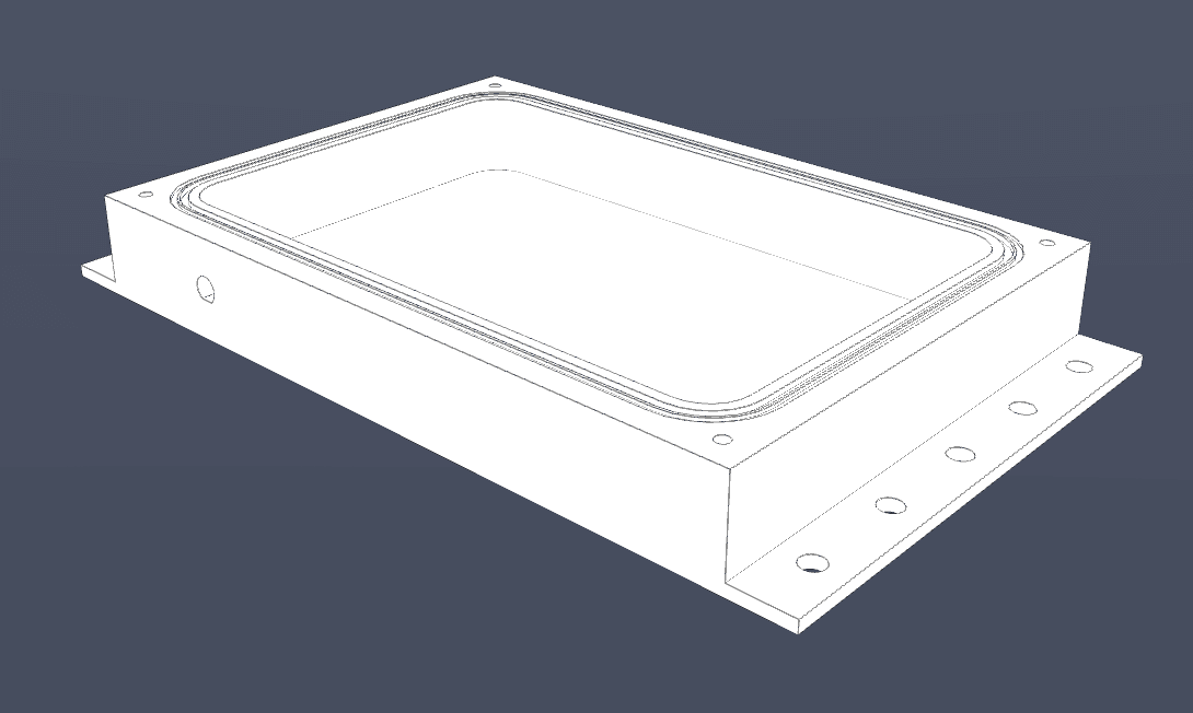
Finally, for the PCB housing design, I used an old design for a different PCB housing and modified it to include RF ports, and different dimensions to accommodate the new PCB. I also modified the mounting flange so that the housing would not be mounted upside down (which was problematic for the old box because of wirebonds coming undone and poor thermalization when clamping it upright).
As of now, I'm waiting for the PCB designer to finalize the mounting plan for the PCB (to prevent short circuiting) so I can finish modeling the mounting holes in the housing, and I'm further refining the flange so that it is easier for the machine shop to manufacture.